
 Back to Living notes
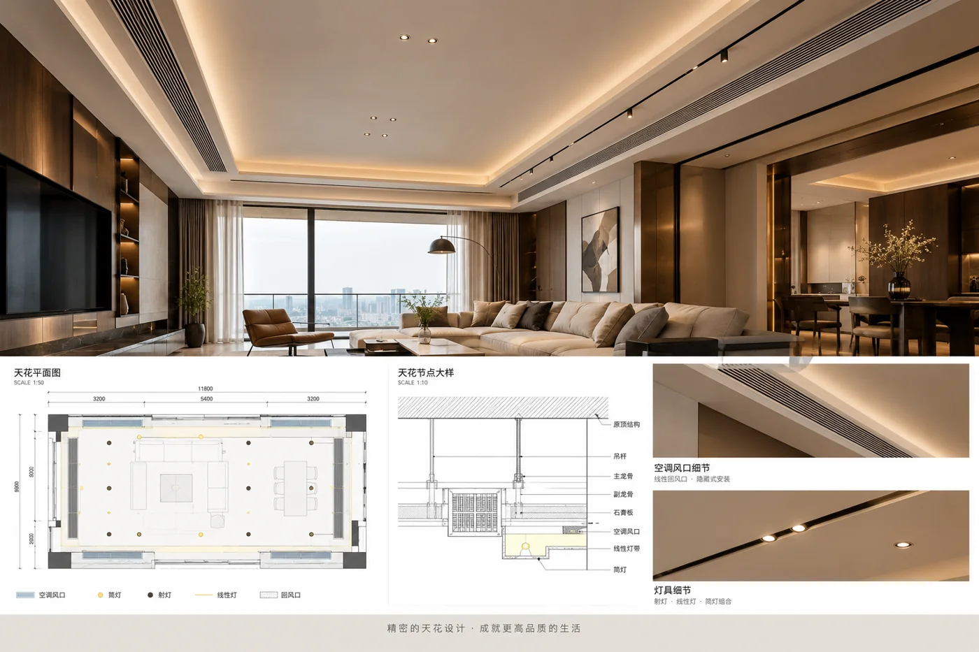
This residential design study of about 180㎡, using New Swan Castle as a topical reference, provisionally sets the structural slab soffit at 2950mm and compares a full-area suspended ceiling with a local equipment band. The area, heights and usage scenarios are all research inputs and do not correspond to an on-site survey or a delivered project. The discussion focuses on how construction layers consume height, and how much height remains in the central stay area once equipment is concentrated.
First establish the beam positions and the target for seating and lying areas
The original scheme recorded the conditions as a 2950mm slab soffit, a 300mm main beam depth and a 2650mm beam soffit; air conditioning, fresh air, condensate water, refrigerant, conduit and maintenance access all need to enter the ceiling at the same time. Before detailing, a unified re-measurement to finished surfaces must be carried out.
Two approaches:
- Full-area suspended ceiling: adding up the construction layers per the original scheme, the finished surface is derived as 2620mm.
- Equipment band approach: pipes and ducts are concentrated into a 400mm band along the wall, leaving the center as an exposed soffit.
In this round the proposed minimum for long-term seated and lying positions in the center is 2850mm; this is the design target for this project, not a general regulatory conclusion.
Write out the construction thickness layer by layer
Compare from slab soffit to finished surface according to the table below; the figures are values for this round of the scheme, and actual equipment and construction details need separate confirmation.
| Layer | Item | Occupancy (mm) | Nature |
|---|---|---|---|
| Baseline | Structural slab soffit to finished floor | 2950 | Scheme baseline; verify on site at 5 points |
| A | Air conditioning/fresh air duct (narrow flat duct 200 high × 400 wide) | 200 | When comparing different duct cross-sections, the equipment specialist should check air volume, air velocity, resistance, noise and maintenance conditions together; equivalence cannot be assumed merely from similar cross-sections |
| B | Duct insulation | 20 | 20mm is a calculation input; the insulation thickness required to prevent condensation should be calculated based on materials, equipment and operating conditions |
| C | Condensate drainage slope allowance (1% slope, most unfavorable point) | 30 | 30mm is a calculation allowance; the actual slope and pipe length are to be confirmed according to the equipment and specialist design |
| D | Framing + double-layer gypsum board + curved transition layer | 80 | 80mm is used for comparing occupancy; the number of layers, connections and load-bearing capacity cannot be inferred from this |
| E | Slab soffit primer + thin coating (exposed soffit area only) | 20 | 20mm is the finish occupancy assumption for this round; the actual substrate and workmanship must be verified |
Full-area suspended ceiling (conventional approach): 2950 − 200 − 20 − 30 − 80 = 2620mm.
Equipment band: same as above, 2620mm.
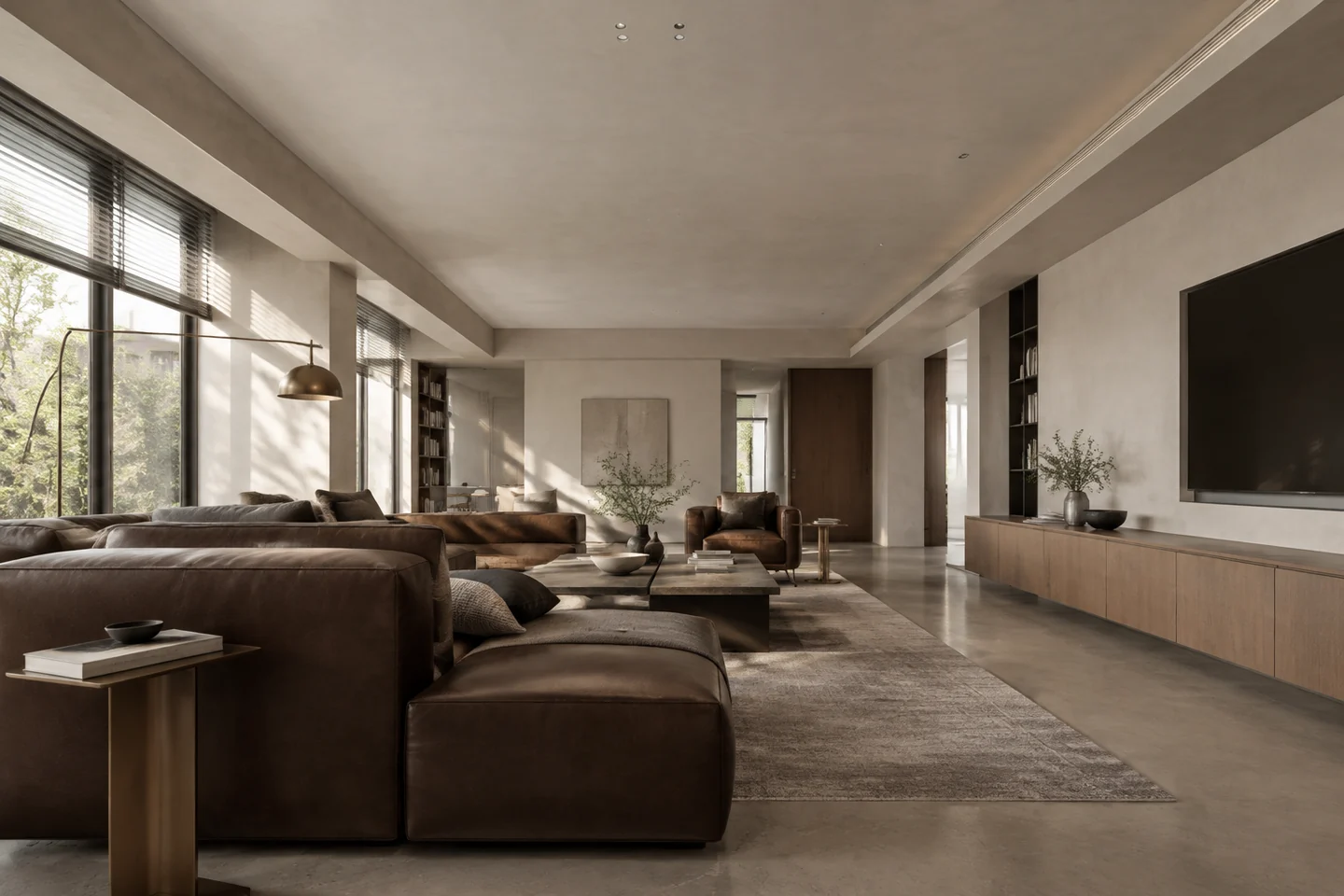
Central exposed soffit area: 2950 − 20 = 2930mm (deducting only the E thin coating layer).
The central 2930mm and the equipment band 2620mm differ by 310mm. The originally proposed 400mm equipment band width still needs to account for insulation, supports and hangers, construction and maintenance allowances.
A to D totals 330mm, while the center deducts only the 20mm thin coating, so the two differ by 310mm. 深圳市熹合空间设计有限公司 concentrates the height loss on the wall side, first leaving the higher ceiling surface for the sofa and work area. Only after doing residential work can one understand living; this allocation must also give space for filter removal, duct insulation and condensate discharge.
Heights at different locations, compared by zone
Because dwell time and equipment conditions differ, each zone is compared separately in the table below. The target values and concession values in the table need to be unified on the same final set of drawings and cannot be regarded as confirmed minimums at the same time.
| Zone | Research target (mm) | Alternative comparison value (mm) | Basis for judgment |
|---|---|---|---|
| Directly above sofa and bed seating/lying positions | 2850 | No concession | Long-term stay; overhead pressure is most sensitive here |
| Corridors and brief standing areas | 2650 | 2620 | Line of sight does not fall on the ceiling |
| Dining and kitchen seating area | 2650 | 2620 | Aligned with air outlets and light strips |
| Above kitchen countertop | 2450 | 2400 | Dense equipment and flues |
| Entryway | 2400 | 2380 | Circulation space |
| Bathroom/shower area | 2350/2200 | Separate minimums | Beyond body dimensions, the space's use and current applicable requirements must also be checked |
2850mm is the proposed target for seating/lying areas in this case; other spaces also cannot lower their height merely on the grounds of "brief stay" and must be confirmed in light of use nature, equipment conditions and applicable requirements.
First route the pipes whose slope cannot be changed at will
Gravity drainage, ducts, refrigerant and electrical conduit have different degrees of adjustability; coordination can proceed in the following order, then conflicts checked against beam positions and equipment selection.
- Gravity drainage: first check the slope and the most unfavorable position.
- Fresh air main duct: compare cross-section and routing in light of air volume.
- Air conditioning condensate branch pipes: reserve per the original scheme's 1% slope, then check against equipment requirements.
- Refrigerant copper pipes: arrange in line with bendable routing conditions.
- Electrical conduit and light coves: position after the integrated routing is confirmed.
- Terminal air outlets and access panels: confirm according to equipment positioning and cover-opening needs.
In principle, first secure the slope required for drainage, then compare the positions of bendable pipes; whether they can run side by side should be determined by the actual cross-sections and support/hanger space.
If thin pipes take position first and large-section ducts arrive later, detours or local stacking may increase. Coordinating in the integrated drawing in advance helps reduce on-site ad hoc lowering of the ceiling.
Once equipment is concealed, terminals and maintenance access must still be usable
The following are the positioning targets for air outlets, light strips and maintenance access in the original scheme, to be reviewed against specific equipment and on-site performance:
- Check the supply air direction together with the positions of the sofa, bed and dining table; the equipment specialist determines the terminal scheme based on airflow organization and operating conditions, and fixed distances or deflection angles are not used to guarantee no direct draft.
- The supply-return air relationship is determined by equipment layout, airflow path and spatial conditions; whether short-circuiting occurs cannot be judged by a single spacing alone.
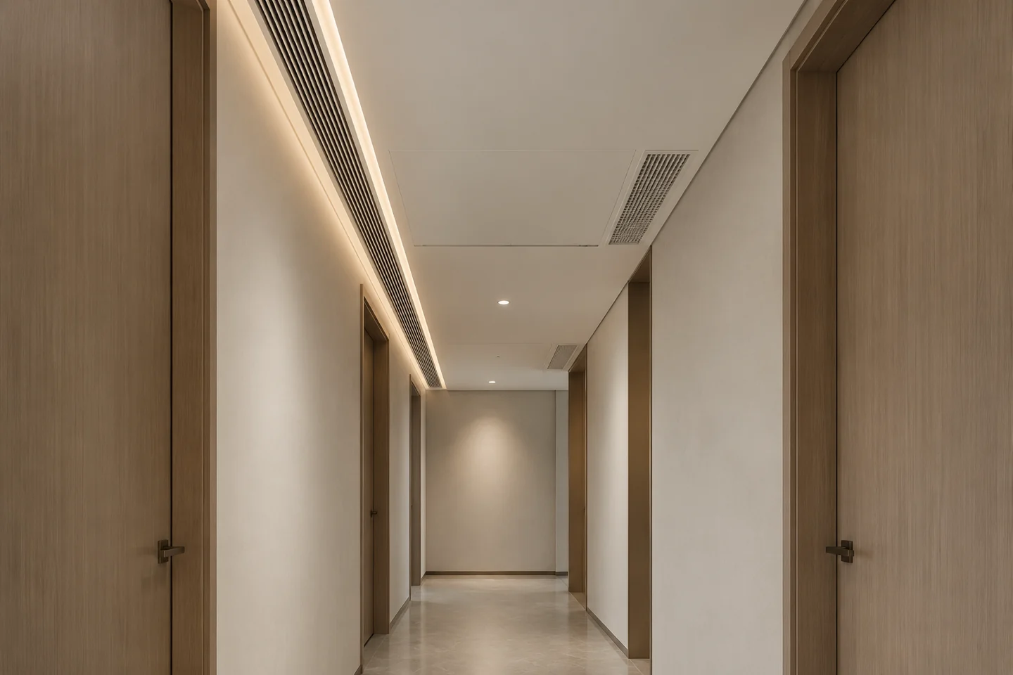
- Light strips and air outlets on the same positioning line: only two lines appear on the ceiling
- Access panels are determined by the actual equipment's maintenance instructions, cover-opening direction and component removal dimensions, and the standing, operating and carrying space below must be checked.
- The brightness relationship between ceiling and walls must be judged in light of material reflection, luminaire distribution and on-site observation; a fixed ratio is not used to guarantee the spatial feel
- Air volume, air velocity, cross-section, resistance and noise should be calculated together by the equipment specialist; without selection and operating-condition data, no uniform air velocity threshold is specified.
Curved edge radius, confirmed separately for each specific construction
The curved edges between the equipment band and the central ceiling surface are proposed to use a microcement finish. The curved edge itself and prefabricated gypsum cornice are different components, and one minimum radius cannot be applied to both.
- In this case the curved edge is proposed to take a 300mm radius; whether this is feasible requires a 1:1 mock-up to check the substrate, finish and joints, and this cannot guarantee freedom from cracking.
- The original prefabricated gypsum cornice approach is compared at one fixing point per 600mm; corners and curved sections need to be confirmed against supplier samples.
- The curvature achievable with prefabricated gypsum cornice should be based on the selected product, factory fabrication data and mock-ups; where there is no corresponding product basis, no uniform factory fabrication minimum is listed.
The 300mm curved edge is retained only as a discussion value for this round of form-finding and must be checked with an actual construction mock-up; it cannot replace the product conditions of prefabricated components, nor does it prove the finish will not crack.
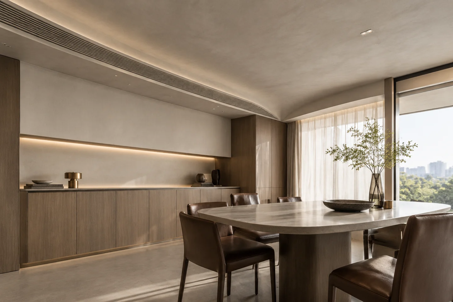
Bring the proposed parameters to on-site verification
The table below lists the basis to be obtained and the verification methods during design coordination. Performance testing and engineering acceptance are carried out by the relevant specialists according to applicable requirements; this study has no completed measurement or acceptance records.
| Verification item | Basis to be confirmed | Verification method |
|---|---|---|
| Zoned clear height | First unify the effective finished surface and measurement positions, then check against the confirmed drawings and applicable requirements, recording unresolved deviations | Laser distance measurement |
| Air outlet discharge direction | Measure after the equipment specialist specifies operating conditions, measurement points and airflow targets; no general comfort value is preset | Anemometer |
| Nighttime noise | Determine applicable targets and measurement methods according to room use, background sound and equipment operating conditions | Sound level meter |
| Support and hanger vibration isolation | The relevant specialist determines inspection locations, methods and records according to construction and equipment requirements | Visual + tactile |
| Curved edge straightness | Check against the confirmed mock-up and the contractor's applicable quality requirements, recording appearance and dimensional deviations | Straightedge |
| Maintenance accessibility | Open and close each one in practice; the filter can be pulled out | Manual test |
Once the calculation holds, it must still be installable and maintainable
Detailing requires further confirmation of four sets of relationships:
Whether the calculation of the equipment band A to D occupying 330mm and the central thin coating occupying 20mm matches the actual construction and beam positions.
Whether the clear height targets for each zone are unified and meet the project's use and relevant specialist requirements.
Whether the pipe routing order can avoid the structure, and whether gravity drainage has sufficient slope allowance.
Whether air outlets, light strips and access panels can be positioned in coordination while maintaining sufficient space for opening covers and removing equipment.
Clear height is not just a set of numbers for the finished surface. The space actually used when sitting down, looking up and changing filters should be considered together with the equipment list on the drawings.
Conditions still to be confirmed later
- Flat duct selection assumes equivalent air volume; flat ducts of different brands may have different cross-sections for the same air volume and must be reviewed against actual equipment parameters.
- The radius of the curved transition depends on the contractor's workmanship capability; 300mm is the value for this case, not a general minimum.
- The noise verification does not account for outdoor unit vibration transmission and structure-borne sound; actual results must be based on on-site measurement.
- This derivation is based on the height condition of a 2950mm slab soffit to the proposed finished surface. For another residence, beam positions, equipment and construction occupancy should be recalculated; a certain floor-height threshold cannot be used to prejudge suitability for an exposed soffit.
This article uses proposed data from a 180㎡ residential scheme to explain the calculation method; the values and construction are not directly applicable to other projects.
