 Back to Living Notes

From communication to drawing production and then to on-site support, each stage needs to make clear what has been confirmed and what still awaits judgment. As materials are updated accordingly, the team and the owner can continue working from the same basis.
The following nine stages illustrate how 深圳市熹合空间设计有限公司's services connect. The specific scope is as agreed in the contract; work can be coordinated and advanced once prerequisites are clear, without mechanically requiring everything to proceed fully in sequence.
Nine-Step Overview
| Step | Name | Core output | Entry condition |
|---|---|---|---|
| Step One | Site measurement and re-measurement | Measured drawing of the original structure | Design contract takes effect |
| Step Two | Requirements brief | Item-by-item numbered requirements parameter table | Site measurement and re-measurement completed |
| Step Three | Concept scheme | Floor plan drawings, circulation verification drawings, functional density calculation table | Requirements brief finalized |
| Step Four | Detailed design | Comprehensive ceiling drawings, elevation development drawings, node detail drawings, MEP terminal positioning drawings | Concept scheme finalized |
| Step Five | Material sample sealing | Sample sealing ledger | Detailed design completed |
| Step Six | Construction briefing | Briefing minutes | Full set of drawings and sample sealing ledger completed |
| Step Seven | Milestone inspection | Inspection record forms for each milestone | Contractor completes the corresponding milestone |
| Step Eight | Furniture placement and pre-inspection | Placement records, pre-inspection checklist | Completion of construction |
| Step Nine | Handover archive | Full set of project handover archive | Pre-inspection passed |
Changes in an earlier stage may affect floor plans, ceilings, MEP and materials. Confirming key conditions and recording versions helps address issues when the impact of adjustments is relatively small.
Step One: Site Measurement and Re-measurement
On site, measure wall by wall and section by section, recording the original structure, beam positions, window positions, drainage points, strong and weak current box locations, and equipment conditions. The prior input is the floor plan provided by the developer: for reference only, not to be used as a design basis.
The measured drawings record structure, beams and windows, drainage and equipment locations; the plan distance and elevation of pipe openings are marked separately. The scheme example uses a key dimension of ±10mm as a verification example; actual precision and methods should be confirmed according to the project and subsequent professional requirements.
In the same area, a total of 5 positions at the four corners and the center can be compared. The scheme example of a 20–30mm height difference is only a scenario of concern; actual conditions are subject to the measurement records, and it cannot be presumed that the floor slab has this deviation.
The measured data complete the design review, and unconfirmed structural or equipment conditions are marked separately.
Step Two: Requirements Brief
What this step does: interview each permanent household member separately, translate living conditions into verifiable spatial parameters, and number them item by item to form a requirements brief.
The brief may include number, behavior, spatial conditions, equipment parameters, verification method and ownership. The scheme example of 20–30 items is a scale reference; the number of items expands with the household information.
Each requirement should clearly state for whom it is, what it responds to, and which drawing carries it, and should be confirmed by the household. Content still lacking dimensions or equipment information is clearly marked as pending verification, rather than being filled in as definite parameters first.
The brief may be changed, but each change must retain the version date, the confirmer, and the list of differences from the previous version. After finalization and the owner's signature, this step is complete.
Step Three: Concept Scheme
Based on the requirements brief and measured data, complete the floor plan functional zoning, circulation planning and functional density calculation.
The floor plan explains functions and furniture; the path diagram discusses the relationship between pedestrian movement, light and household services; the storage and area list helps verify requirements. There is no need to repeatedly express the same thing just to pad the number of outputs.
Bring each item of the brief back into the scheme to see whether a spatial response already exists and which conditions still require trade-offs. Not every item can be satisfied without cost; unmet content should continue to be discussed with the household.
This step is complete after the floor plan scheme is reviewed and confirmed by the owner and signed as final.

Step Four: Detailed Design
Detailed design proceeds in two sub-steps.
Ceiling detailing first compares the heights of different zones, then integrates air conditioning, fresh air, lighting and maintenance access. The scheme examples of 2850mm for long-term, 2750mm for medium-term and 2650mm for short-term are example targets and cannot be applied as a clear-height red line for all residences; actual values are determined jointly by structure, equipment, applicable requirements and household use.
Then carry out elevation and node detailing. Project the floor plan scheme and ceiling scheme onto the four elevations to complete the detailed design of wall forms, storage elevations, switch and socket positioning, and elevation material joints. The outputs are elevation development drawings (developed in four directions, with dimensions, materials and closure methods marked), node detail drawings (enlarged detail drawings of key closure methods), and MEP terminal positioning drawings (precise positions of switches, sockets and panels).
Ceilings, elevations and equipment points are reviewed by the design side, and specialized content is confirmed by the corresponding professionals.
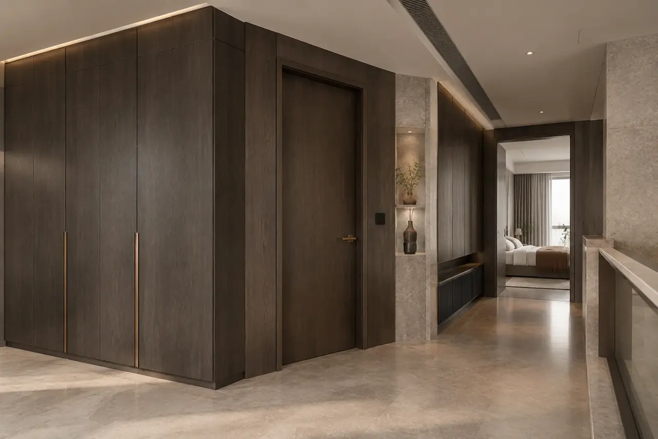
Step Five: Material Sample Sealing
According to the material schedule in the detailed drawings, complete the selection, numbering and sample sealing ledger compilation of all main materials, and obtain the owner's signature for confirmation.
The sample sealing ledger records the number, material, location, color code, texture and gloss. Where material differences require it, a separate sample of the allowable range is kept to explain the acceptable boundary together with the reference sample.
Compare samples under natural light and actual lighting, verify positions and junctions, and then form a confirmation record.

Step Six: Construction Briefing
The design side and the construction side hold a briefing meeting, going through questions drawing by drawing; the construction side raises difficulties that may be encountered during construction, and the design side replies item by item.
The output is the briefing minutes: recording every question raised by the construction side and the design side's replies, signed by both parties. All drawing questions are recorded and answered item by item, the construction side has understood the key node methods, and the sample sealing numbers are formally handed over to the construction side.
When discussing the briefing, verification can begin with the following three types of information: the correspondence between sample sealing numbers and use locations, the operating space requirements for access panels, and the boundary of the work scope of a lump-sum contract. This step is complete after both parties sign for confirmation.
Step Seven: Milestone Inspection
Attend key construction milestones on site and verify item by item against the drawings and sealed samples.
At the agreed milestones, separately verify pipeline and equipment points, wall positions, clear heights, materials and furniture relationships. Construction quality and specialized tests are carried out by the responsible units, and the design side keeps verification records within its scope.
Each record states the location, basis and handling result; when differences are found, the relevant parties confirm the adjustment and re-verify.
Step Eight: Furniture Placement and Pre-inspection
After the hard fit-out is completed, position the movable furniture and soft furnishings, and conduct a pre-acceptance inspection of the finished surfaces.
The outputs are placement records (the actual placement position of each piece of furniture compared with the scheme) and a pre-inspection checklist (detail items on finished surfaces that need adjustment). Furniture placement positions are consistent with the scheme, and each item in the pre-inspection checklist has rectification requirements and completion deadlines.
Once the furniture is placed, it is also necessary to see how people pass by when a chair is pulled out, and whether reaching for a book will bump into the person next to you. 深圳市熹合空间设计有限公司 treats these actions as part of placement verification: only after doing residential projects can one understand living, and dimensions need to be looked at once more within real usage relationships.

Step Nine: Handover Archive
Organize and archive the documents from the entire project process to form a complete project handover archive.
The archive may, as per the contract, compile the requirements brief, design measurement data, drawings of each stage, sample sealing records, briefing minutes and design changes; engineering acceptance records, as-built construction drawings and completion photos are provided by the corresponding responsible parties with sources marked. The catalog should list the versions actually received, confirmed items and materials still to be supplemented. A complete set of design documents does not mean engineering acceptance has passed, nor does it mean every document was issued by the design side.
The handover archive retains the drawings, changes and records actually produced, for future maintenance. The catalog should clearly define the scope of materials and must not describe construction records that have not yet been produced as already available.
How Prerequisites Affect Subsequent Work
When key requirements, dimensions and equipment conditions are not yet clear, subsequent drawings may be repeatedly adjusted. Work on the confirmed parts first while marking pending items and confirmation points, so that parallel work also has clear boundaries.
The earlier the mutually affecting conditions are identified, the easier it is to compare adjustments. Version and responsibility records help changes be passed on to all relevant drawings.
The Relationship Between This Process and "Separation of Design and Construction"
深圳市熹合空间设计有限公司 provides residential design-only and design implementation support, and does not undertake construction. Which stages and to what depth are specified in the contract.
The design side verifies the agreed design intent, the construction side bears construction management and quality responsibility, and equipment, structure and specialized testing each belong to the corresponding responsible professionals. Design support cannot replace statutory engineering supervision.
The boundary between the two is clarified in the form of briefing minutes during the construction briefing.
This process is used to explain how services connect; specific materials and site records are produced as the actual project progresses.
