 Back to Living Notes
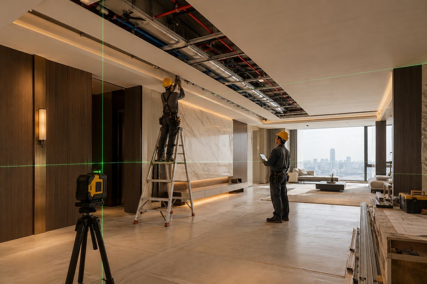
When an air outlet sits close to seating, or maintenance access is blocked by cabinetry, it is often not a problem of a single piece of equipment but of furniture, structure and ceiling not being checked together. The finished height needs a clear calculation basis before installation.
深圳市熹合空间设计有限公司 First compare clear heights by zone, then lay out equipment and maintenance routes together. Only after working on homes can one understand living: whether the space overhead feels open when reading by the window, and whether the filter can still be removed years later, both need a place in this set of drawings.
What ceiling coordination detailing solves
A ceiling may accommodate air-conditioning units and ducts, fresh air, lighting, maintenance access, curtains and applicable fire-protection terminals. Concentrated equipment such as underfloor heating manifolds should be positioned according to system requirements and must not be assumed to belong on the ceiling.
Each of these systems has its own dimensional, spacing, installation-direction and maintenance requirements. If each system is drawn and installed separately, the actual situation on site is ducts crossing and clashing, clear height compressed layer by layer, and access panels ending up in positions where they cannot be operated.
The coordination drawing expresses position, elevation, airflow and maintenance relationships together, with conflicts referred to the relevant disciplines for confirmation, so that the finished surface corresponds to real use.
The logic of setting the clear-height line first
Clear height is jointly determined by the existing structure, use and applicable requirements; design preferences need to be compared within feasible conditions.
The three groups of targets listed below by dwell pattern are retained from a scheme example and serve only as a scheme example. Actual clear heights need to be re-determined in light of structure, equipment and project requirements:
| Zone type | Original scheme target | Basis |
|---|---|---|
| Long-dwell positions (bedroom, living-room sofa area, study seating area) | 2850mm (example) | Long dwell in sitting and lying areas; too low a clear height creates a sense of pressure |
| Medium-dwell positions (dining room, kitchen work area, study standing area) | 2750mm (example) | For activities lasting 30-90 minutes, clear height needs to remain comfortable |
| Short-passage positions (corridor, entryway, walk-in closet passage) | 2650mm (example) | Brief passage; clear height may be appropriately lowered but not below the target confirmed for this project |
Dwell time is one dimension for discussing scale; furniture, sightlines, movement and building conditions must also be considered, and a uniform height cannot be mechanically assigned by duration.
First unify the elevation datum between the structural slab soffit and the finished floor, then check equipment, supports and hangers, insulation, slopes and finishes. They may overlap or be offset, and one cannot assume they simply subtract layer by layer.
The scheme example lists ductwork at 200–350mm, indoor units at about 200–250mm, fresh-air ducts at 100–200mm, lighting conduits and framing at about 50–80mm, and gypsum board at about 12mm or double-layer 24mm as height references. Actual dimensions and overlap relationships are subject to the selected equipment and construction.
When the finished height does not meet the target, first compare routing, equipment type and plan adjustments. Duct diameters must not be directly reduced just to gain height; airflow, pressure, noise and maintenance conditions must be reviewed by the equipment discipline.
How to establish priority among conflicts
The so-called yielding relationship means clarifying in advance on the drawings which conditions cannot be changed and which can be coordinated.
Mandatory conditions such as structural safety and fire protection are confirmed first, and equipment performance and maintenance space must also be met. The scheme example uses 600mm in front of maintenance access as a reference; actual requirements are checked against equipment disassembly and assembly needs. The relationships among main ducts, indoor units, fresh air, lighting and curtains are coordinated jointly by the relevant disciplines; smoke and heat detectors must not be listed as the last items to yield to the design form.
Once confirmed, the relationships go into the coordination drawing; when changes occur on site, the corresponding discipline re-checks them, avoiding a situation where whichever party installs first fills the space and other equipment is then forced to yield passively.
Common conflicts and solutions
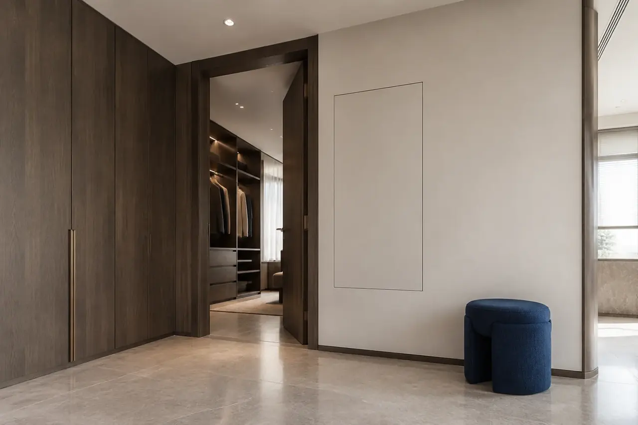
When the maintenance location conflicts with cabinetry, it is necessary to look at both where the equipment can be serviced from and how the panel opens. Options such as adjusting the equipment or cabinetry, or reserving a removable interface, can be compared, but one must not simply move the access panel away and leave equipment that cannot be reached.
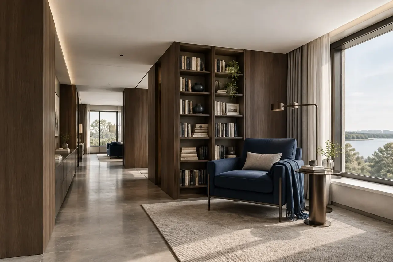
When supply air conflicts with the sofa or head of the bed, draw the actual furniture and long-term sitting and lying positions into the drawing. Supply-air direction, airflow rate, temperature and operating conditions need to be judged together, and the equipment discipline then checks the airflow impact; comfort cannot be promised based on a single plan-view avoidance distance.
When ducts meet beams, first study existing usable paths and detours. Holes must not be arbitrarily cut in existing beams; any scheme involving structural provisions or modifications must first be confirmed by the structural discipline, then checked for airflow, noise and duct length.
When light apertures conflict with framing, locate them jointly on the drawings first. The scheme example's 100–200mm light-position adjustment is only a comparison range; moving luminaires or adjusting framing construction both require checking against lighting and ceiling requirements, and must not be cut directly on site.
Where the corridor and living room have different heights, routing, equipment and ceiling transitions can be compared, but requirements must not be lowered simply by renaming a function. The scheme example's 2650mm is an example target; actual passage and dwell conditions still need to be met.
How the ceiling coordination drawing connects with the floor plan
Only after furniture positions are clear can supply-air avoidance and long-term dwell be judged; only after equipment models, routing and maintenance requirements are clear can the ceiling be calculated. The two sets of information should be cross-checked against each other.
The output of the ceiling coordination drawing also feeds back into the floor plan: if the clear height in a certain area is genuinely insufficient, it may be necessary to adjust that area's function, move long-term dwell positions to areas with greater clear height, and change that area into a short-passage position or storage space.
When the plan genuinely needs adjustment, bring the cost and impact back to the household for confirmation of needs. Equipment, space and use need to hold together jointly, rather than any one party yielding unconditionally.
Deliverables of ceiling coordination detailing
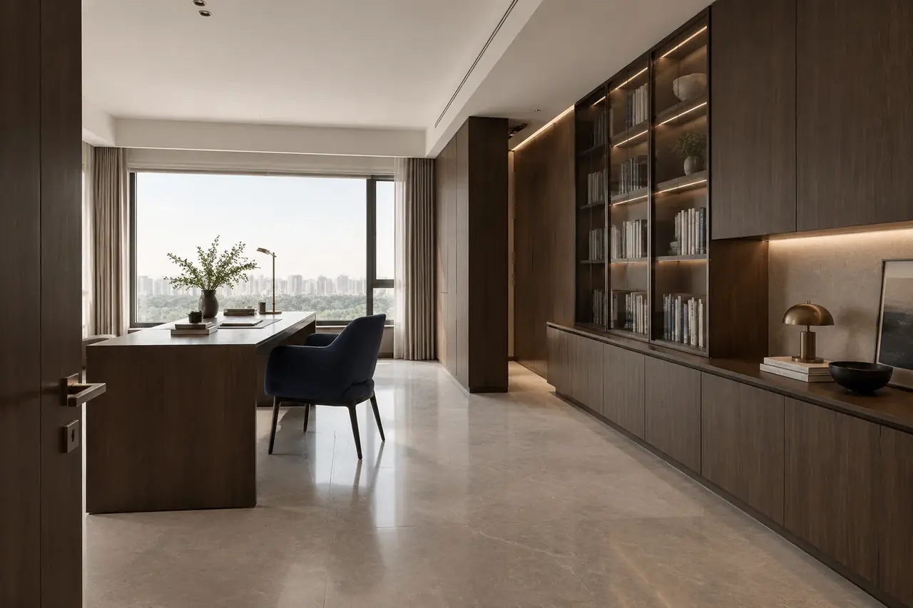
The coordination drawing should retain structural and finished-surface elevations, equipment positions, routing, lighting, maintenance access, conflict coordination and the corresponding check results. The scheme example's 600mm maintenance clearance must be checked against the equipment, and the three height groups are also determined by this project's conditions.
Before closing up, inspect the site against the confirmed drawings, and update changes to the corresponding version as a basis for subsequent maintenance.
The three questions this method answers
The starting point is the existing building and actual use, then the clear-height target and equipment conditions are compared together.
The respective conditions of structure, fire protection, equipment and maintenance are clarified first, and then the relevant disciplines coordinate the parts that can be adjusted.
When a height conflict arises, re-compare routing, equipment or furniture arrangements and record the confirmed changes; one cannot close out after completion merely by accepting inconvenience.
The dimensions in this article come from the original scheme example and are used to explain the checking relationships. Specific values adopted are confirmed by the project drawings and the corresponding disciplines.
